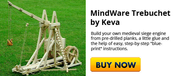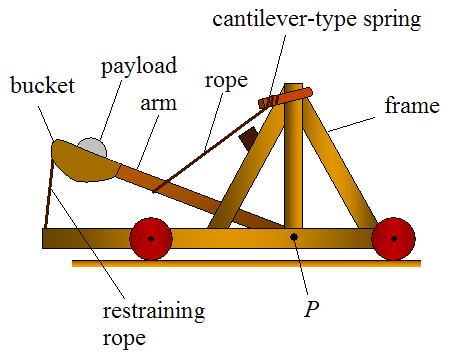
These instructions will tell you how to construct a small to medium sized French counterweight trebuchet in your own backyard; it should be roughly capable of slinging a baseball, tennis ball, full beer can, or similar such projectile 50-100 yards with ease!
Now, precisely what I’m going to give you instructions on how to build is a working model of the famous French trebuchet and is based on the principles of the hinged counter-style weighted trebuchet. It has an overall base of 34 in x 31 in.
The following information will give you complete instructions regarding the materials needed, other materials (optional), joining procedures, line drawings with dimensions, making the pouch, and how to put it all together. Below I’ve got an excellent video explaining the science behind them and how they work:
Materials:
- 5 in x 1/8 in round strong steel rod
- 2 steel pipes, 1.58 in x ½ in diameter, with slip fit to go over the primary axle of 3/8 in
- 17 in x 3/8 in strong steel rod
- 3 screws, eye variety, ¼ x ¾ in
- 1 x 24.5 oz can (baked bean can is okay)
- 1 ball of very strong brown twine, not packing variety
- 4 pieces wood 1 in x 1 in x 46 in
- 2 pieces wood 1 in x 1 in x 7 in
- 2 pieces wood ½ in x ¾ in
- 1 piece wood ½ in x ¾ in
- 2 pieces wood ½ in x ¾ in
- ¼ in round x 22 in x 1.17 in wooden molding
- 2 pieces 4 in Velcro
- 2 pieces wood ½ in x ¾ in
- 2 pieces wood ½ in x ¾ in
- 2 pieces wood ½ in x ¾ in
- 2 pieces wood 1 x ¾ in x 7 in
- 2 pieces pole style wood ¾ in diameter x 1.58in
- 1 x 6 in x 8ft x ¾ in wooden board without knots
Preparation:
- Cut the first steel rod into 2 pieces, measuring 3 in and 2 in only.
- Cut the second steel rod into 3 pieces, measuring 3.5 in, 6.5 in and 7 in.
- Cut the first 4 pieces of wood to lengths of 34 in.
- Cut the first 2 pieces of wood to lengths of 24.75 in.
- Cut the second 2 pieces of wood to lengths of 10.5 in.
- Cut the first 1 piece of wood to a length of 31 in.
- Cut the third 2 pieces of wood to lengths of 34 in.
- Cut the fourth 2 pieces of wood to lengths of 11 in.
- Cut the fifth 2 pieces of wood to lengths of 4 in.
- Cut the sixth 2 pieces of wood to lengths of 14 in.
Note:
The final lengths of the ½ in x ¾ in pieces should equal 30 ft 3.5 in.
Cut the board into ½ in pieces as follows:
1 of 1 in x 1 in x 46 in
2 of 1 in x 1 in x 7 in
Keep remaining wood for the base
Tools:
- Electric drill, 3/8 in bit, 1/16 in bit
- Strong scissors
- Elastic bands
- Table saw
- Strong wire cutters
- Regular hammer
- Sharpened punch
- Pliers
- Vise grips
- Strong wood stapler
- Tooth file, fine
- Sandpaper
- Wood stain
- Sealing lacquer
- Knife (optional)
- Eye and ear guards
- Strong working gloves
Method:
Each section is given a name, according to the original names designated to each piece historically.
Main Beam: Create a taper measuring 13.5 in from end 1 to 0.25 in at center, ending with a 0.5 in at other end. The taper begins beyond the axle hole. Drill two holes with the 3/8 in bit, perpendicular to the beam to carry the axles. The first is located 1 in from the thickest end and the second is 10 in from that hole, heading towards the thinnest end. Make two of these only.

Diagram 1: adapted version of measurements for main beam.
The main beam should look like this:

Diagram 2: main beam with drilled holes.
Corner Leg: Use one of the first 4 wooden pieces. This is only one leg, but cuts are made on both sides. Cut half laps ¼ in deep. Mark a measurement of 64.2, ¾ in from edges. Do the same again at 24.48 in points. Mark 1 line, ¾ in away to connect those marks. Or, see the following diagrams:

Drawing 3: examples of leg 1, both sides.
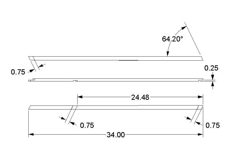
Diagram 4: measurements for cutting and angles for corner leg 1.
Corner Leg 2: Copy the procedures for corner leg 1, creating a mirror image. Create 2 using the remaining first 4 pieces of wood.
Long Beam: Use the third set of 2 pieces of wood for this. Follow the diagrams below to make the necessary cuts and measurements:
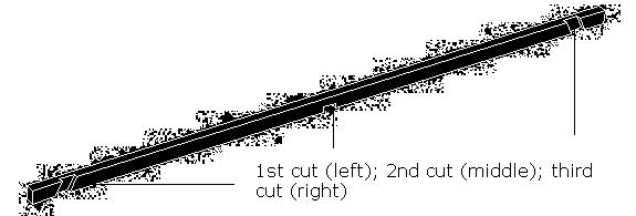
Diagram 5: the long beam cuts as they should appear.
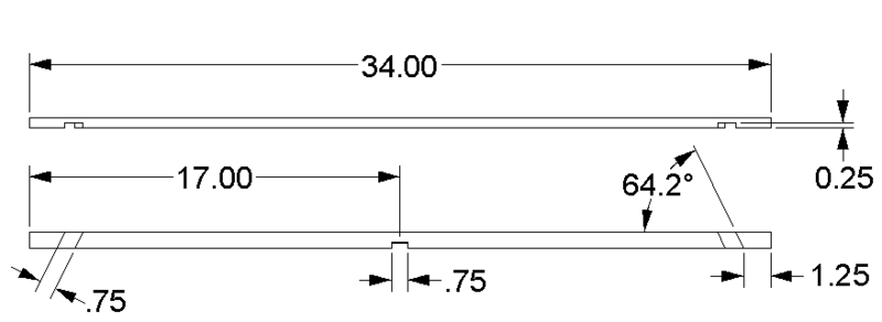
Diagram 6: long beam measurements.
Trough: Use the molding, and staple each piece of Velcro at each end, leaving half the Velcro pieces extending beyond the ends, lengthwise.

Diagram 7: trough drawing.

Diagram 8: trough measurements.
Outrigging Beam: Use the only single wooden piece and create 2 notches, sloped, as follows:

Diagram 9: outrigging beam with notches.
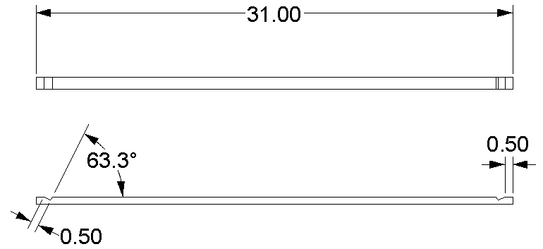
Diagram 10: outrigging beam measurements.
Crossing Beams: Use the second set of 2 pieces of wood, creating 2 x 9″ notches, angles, tilting inwards in the direction of the axle.
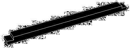
Diagram 11: crossing beam drawing.
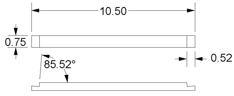
Diagram 12: crossing beam measurements.
Outrigging: Use the first set of 2 wooden pieces, creating two notches at each end.

Diagram 13: outrigging drawing with notches.
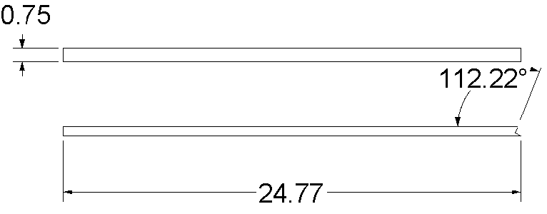
Diagram 14: outrigging measurements.
Hangers: Use the 6th set of two wooden pieces and drill two holes in each end of 3/8 in, 1 in from the ends.
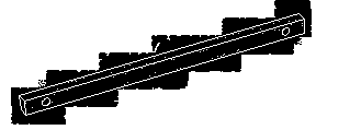
Diagram 15: hangers drawing.

Diagram 16: hangers diagram.
Outrigging Brace and Frame Cap: Use the 4th set of 2 pieces of wood for the outrigging braces and the 5th set of 2 pieces of wood for the frame caps.
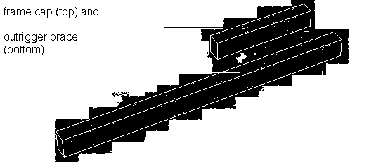
Diagram 17: frame cap and outrigging brace drawing.
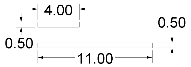
Diagram 18: frame cap and outrigging brace measurements
Beam Brace: Use the 7th set of 2 pieces of wood to measure as follows:
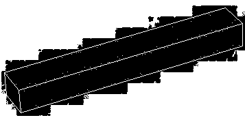
Diagram 19: beam brace drawing
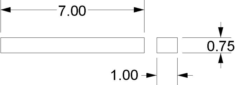
Diagram 20: beam brace diagram
Spacers: Use the 9th set of 2 pieces of wood and find washers to fit on them to hold them in place when so they can properly center the throwing arm.
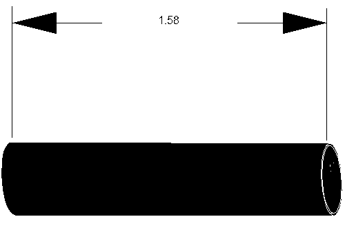
Diagram 21: spacers drawing and measurements
Axles: Use the 3 pieces of 3.5in, 6.5in and 7in steel rods. If you can, cut threads into each end and find nuts to keep them in place.
Counterweight: Drill 2 x 3/8in holes into the can, on opposite sides, near the top. For a firm fit, use washers.
Eye screw: Drill a small hole into the throwing arm beam and insert the screw.
Assembly:
Collect and lay out one piece of each part: leg 1, leg 2, long beam, and outrigging brace and frame cap. Remember that the frame cap must not sit flush against the trebuchet legs. From the bottom of the long beam to the bottom of the outrigging brace, it should measure 22in.
Glue or all the joints together, using elastic bands, counterweights or clamps to keep the joints in place whilst drying, and move onto the matching set. Both sides should be the same and have the same measurements.
Diagram 22: frame drawing
Frame, cross beam, outrigging and outrigger beam assembly: Dry fit cross beams into position. Secure them with elastic bands or clamps. Put outrigging beam in place, centered between the frames. Put the outrigging in position. Move the outrigging beam backwards and forwards until both frames are at the same angle, facing inwards. Mark the positions on the outrigging beams with an HB pencil.
Verify that the frame holes are correct by measuring from the holes to the ground. Both heights should match. If not, move the outrigging beam until they do. When satisfied that all things are in position, glue everything in place and secure them with elastic bands and clamps until dried (overnight).
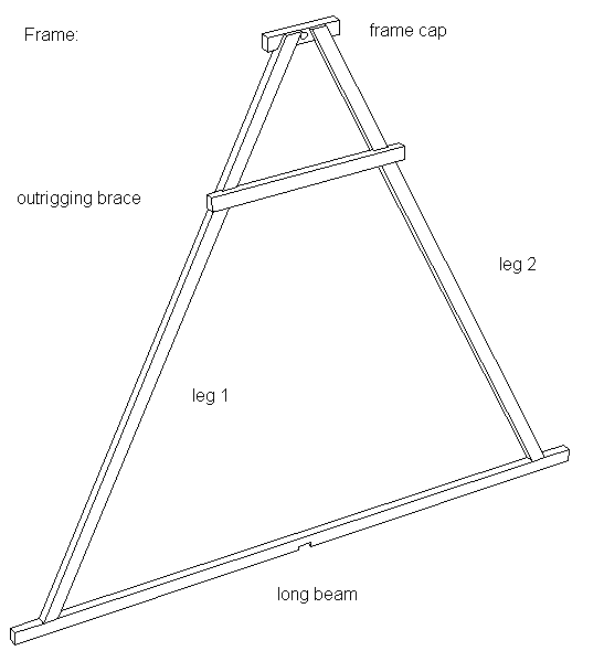
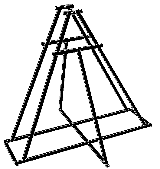 Diagram 23: assembled frames, counterweights and throwing arm drawing
Put the beam braces 6.5in from the ends of the throwing arm. Glue in place, one of the bottom and one on the top. Wrap some twine around the joints to increase the strength. These will protect the throwing arm from breaking near the axle. You may also want to get a release style pin and put it at the top of the assembly or the bottom. This will help you when you are firing, but either one will do.
Begin assembling the throwing arm section by pushing the axle pieces through the holes in the frame. Put a spacer on each end, the throwing arm, and another spacer. Continue this with all the axle sections until complete, adding the pouch on the end (see instructions below diagram for making a pouch).
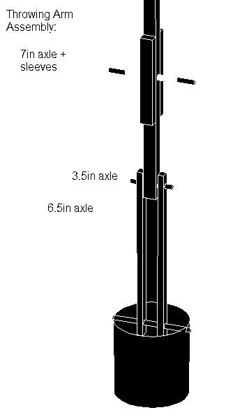
Diagram 24: throwing arm assembly picture
A pouch is an essential ingredient, if you want to throw your dog a ball with a trebuchet. It is easy to make, cheap and long lasting. You need a diamond-shaped medium leather, measuring 5in width x 8in length, with a notch cut into each corner. Sew the created edges together to make a cup or belly pouch. Insert some holes in the longer ends, reinforcing them with grommets (metal) to stop tearing.
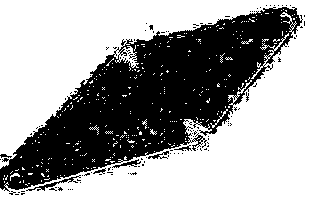
Diagram 25: pouch with grommets drawing.
To prepare the trigger by putting the remaining two eye screws into the center of the back cross beam. Bend a 1/8in x 2in piece of steel into a loop – this is the trigger pin. Secure it with a five foot piece of twine that can be used to set it off from a safe distance. Tie some more twine around the throwing arm section, 2½ in away from the tip and then secure it on the other end with a loop. The loop must be able to fit easily over the trigger pin. The trigger line must be short enough to keep the throwing arm in place on the base or ground until firing.
To prepare the sling, cut some twine into 2 very long pieces, measuring the length from the throwing arm’s axle to the release pin; tie each end (4) to one key ring each. Attach 1 key ring to the throwing arm tip eye screw. Attach another to the pouch’s grommets. Attach the other sling line to the final grommet and key ring. This will for a slip ring that can slide easily over a release pin. Check that the system is working by doing a test fire. Use some small rocks, which you can put in the can.
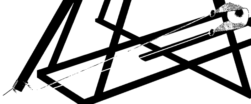
Diagram 26: Projectile in the sling, attached to the throwing arm
Congratulations! You have successfully built a small scale trebuchet that will give you hours of fun for you and your neighbors (you get to fire, they get to duck 😈 ). Don’t use this to build a full scale one as the materials need to be much stronger. Did you know that the firing range on a full sized trebuchet is around 500 yards? Have fun!
Further Reading and Additional Resources
The first thing I’d highly recommend you do if you’re really interested in constructing your own catapult, trebuchet, and/or other similar “backyard ballistics” type of devices is pick up my two favorite books on the subject:
- The Art of the Catapult: Build Greek Ballistae, Roman Onagers, English Trebuchets, and More Ancient Artillery
- Backyard Ballistics: Build Potato Cannons, Paper Match Rockets, Cincinnati Fire Kites, Tennis Ball Mortars, and More Dynamite Devices
Check out my new article on how to build a mini (desktop-sized) catapult out of things you can find around your home or office, you can just buy your own Desktop-sized catapult kit.
Wikipedia Article on Trebuchets
Excellent website where you can follow along as this guy constructs his own Trebuchet; lots of good pictures and would be very helpful to someone wanting to build one:
Dan Becker’s Trebuchet Page
The Grey Company Trebuchet Page
Nice site with sections explaining each particular type of trebuchet.
Desktop Trebuchet for Cubicle Warfare – Gizmodo.com
Video of Rich Englishman Flinging a Piano with his Trebuchet
*Note: these are based off of the plans found at Ripcord’s Trebuchet site at: http://www.ripcord.ws/plans/plans.html, an excellent site totally devoted to trebuchets.
